Stringy
Stringy
Attention ;)
This project is now available at Pimoroni! Click here to go there.
You won’t believe it’s not an actual guitar!
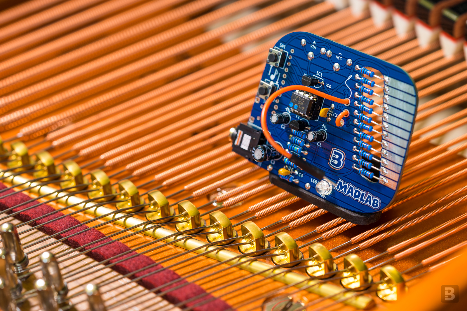
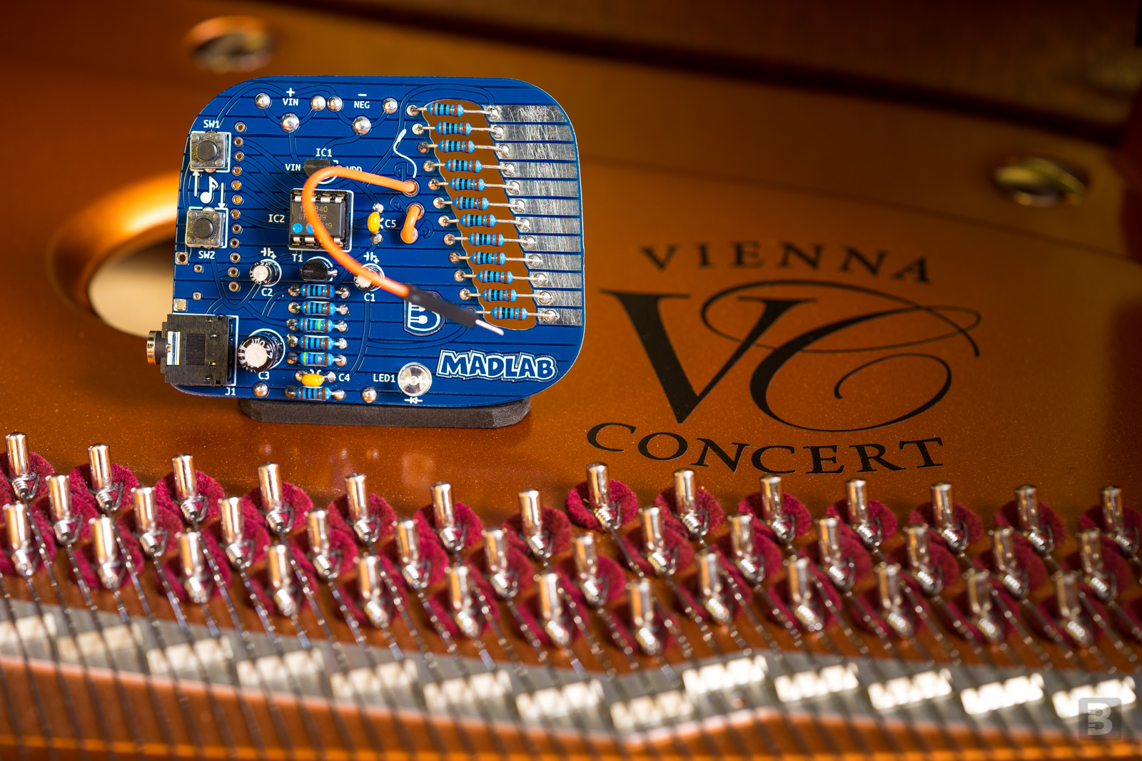
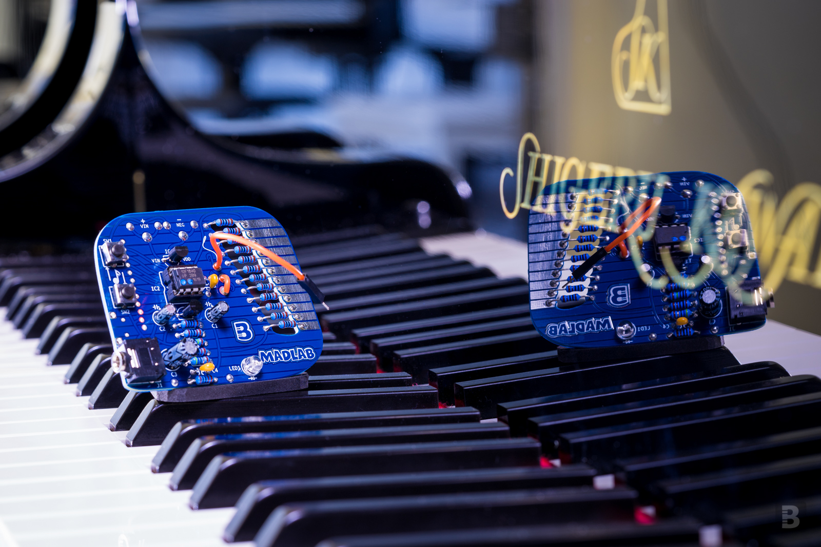
Stringy synthesizes guitar sounds using an efficient implementation of the Karplus–Strong string plucking synthesis algorithm implemented on a tiny PIC microcontroller. It can play notes over five octaves (twelve notes in each octave) in either acoustic or electric guitar sounding style.
This is a collaborative project with James Hutchby from MadLab. We truly admire the ingenuity of James’ work and thank him for allowing us to re-implement his original project.
Stringy was Project #14 of the Boldport Club.
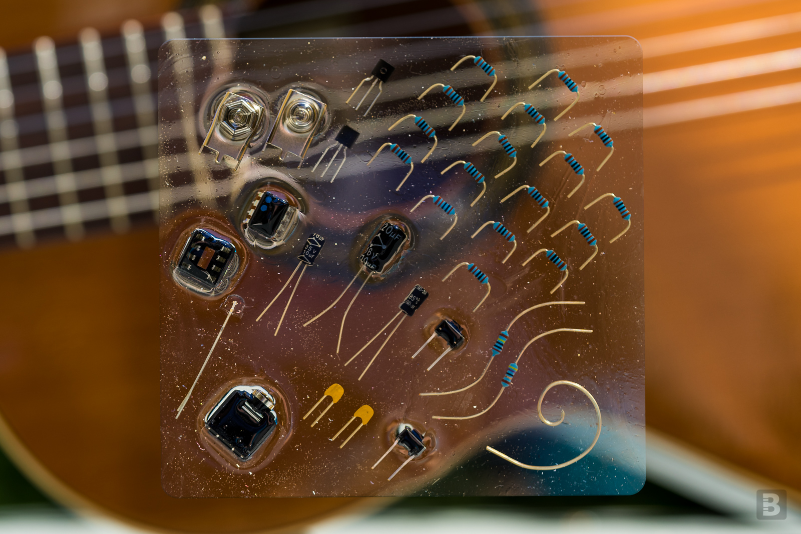
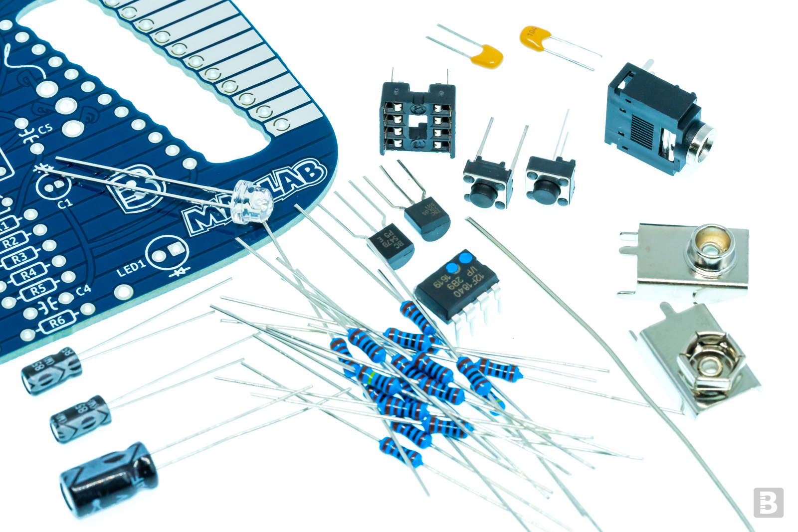
What’s included?
1x PIC microcontroller, Microchip 12F1840-I/P
1x 5V linear regulator, Taiwan Semiconductor TS78L05CT A3G
1x BJT NPN transistor, Diotec BC547B
1x 5mm blue LED, Kingbright L-9294QBC-D
2x Tactile switch, TE Connectivity FSM4JRT
17x 1KΩ resistor, Multicomp MF25 1K
1x 47Ω resistor, Multicomp MF25 47R
1x 1MΩ resistor, Multicomp MF25 1M
1x 220µF electrolytic capacitor, Multicomp MCGPR16V227M6.3X11
1x 10µF electrolytic capacitor, Multicomp MCMR35V106M4X7
2x 0.1µF ceramic capacitor, Multicomp MC0805Y104M500A2.54MM
1x 3.5mm jack socket, TruConnect 20-0137
1x Battery contact positive, TruPower 18-0596
1x Battery contact negative, TruPower 18-0597
1x 8-pin DIL socket, TruConnect DS1009-08
1x piece of 20AWG hookup wire
1x Lovely PCB
Additionally, you’ll need to supply your own flexible wire for the stylus, a 9V battery, and speakers or earphones with a standard 3.5mm plug. If you’d like to power the board from a USB, the footprint on the board is for this component.
Assembly
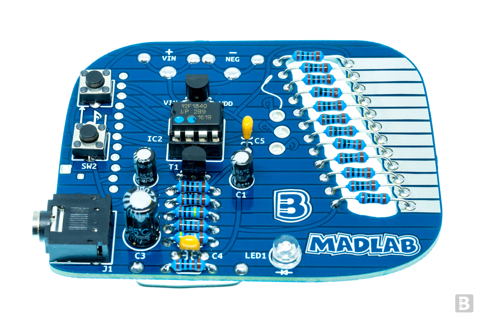
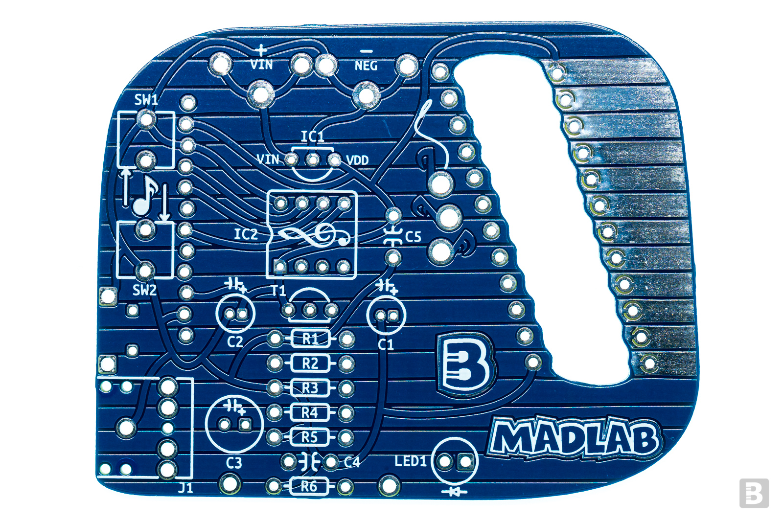
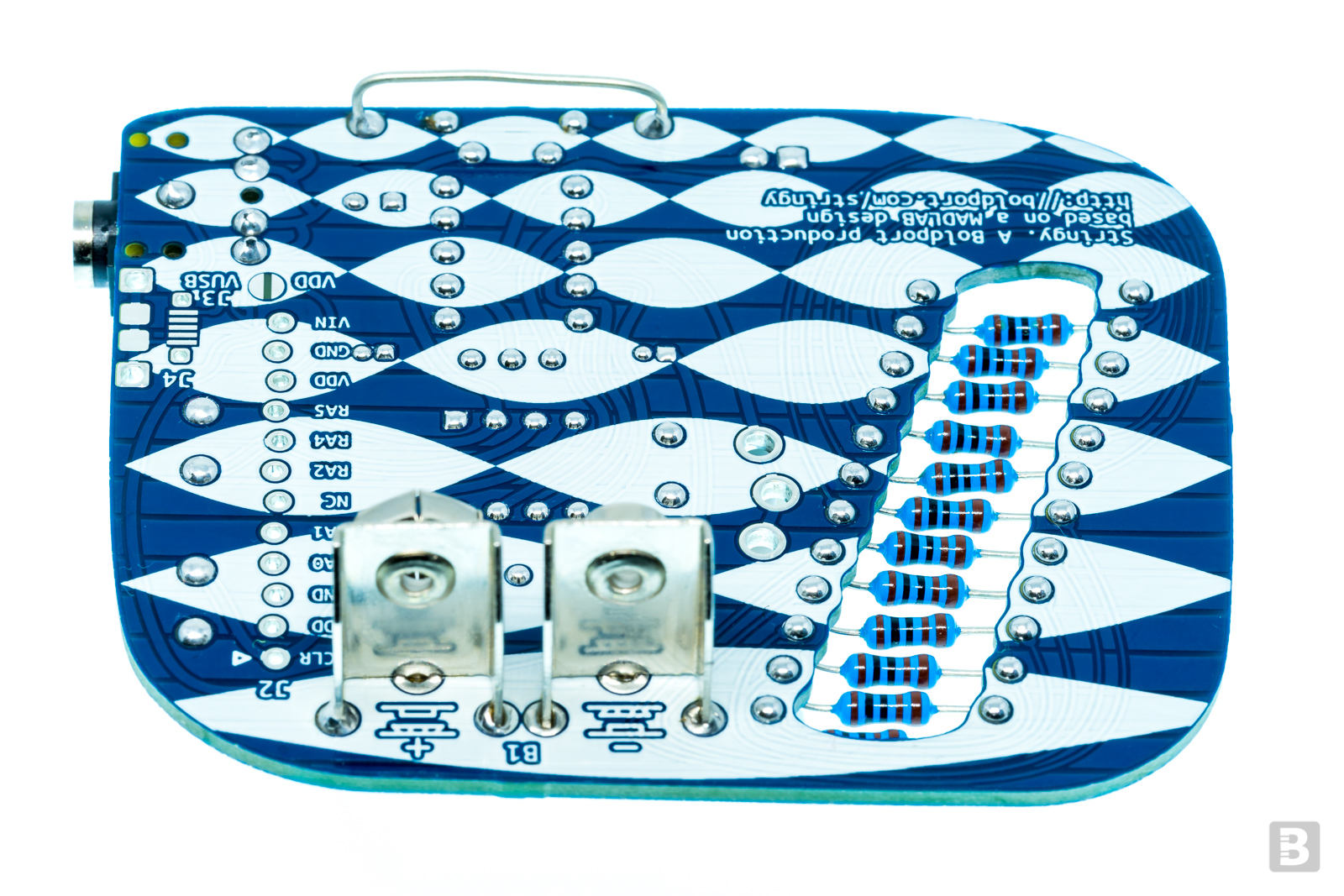
Follow the card that comes with the project for placing the components. Give particular care when soldering C1 and C2 as their positive and negative pins are close together and you definitely don't want them to be shorted. Similarly, check that the pins of the plus and minus battery contacts that are closest to each other contacts are not shorted.
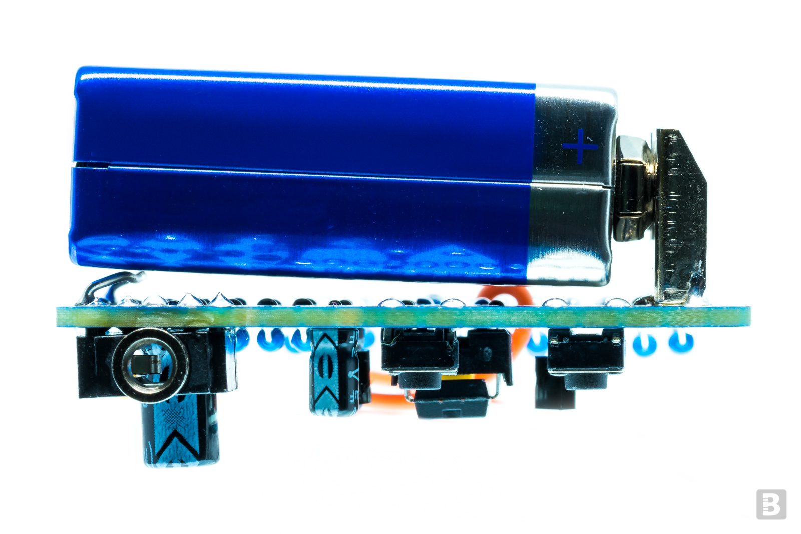
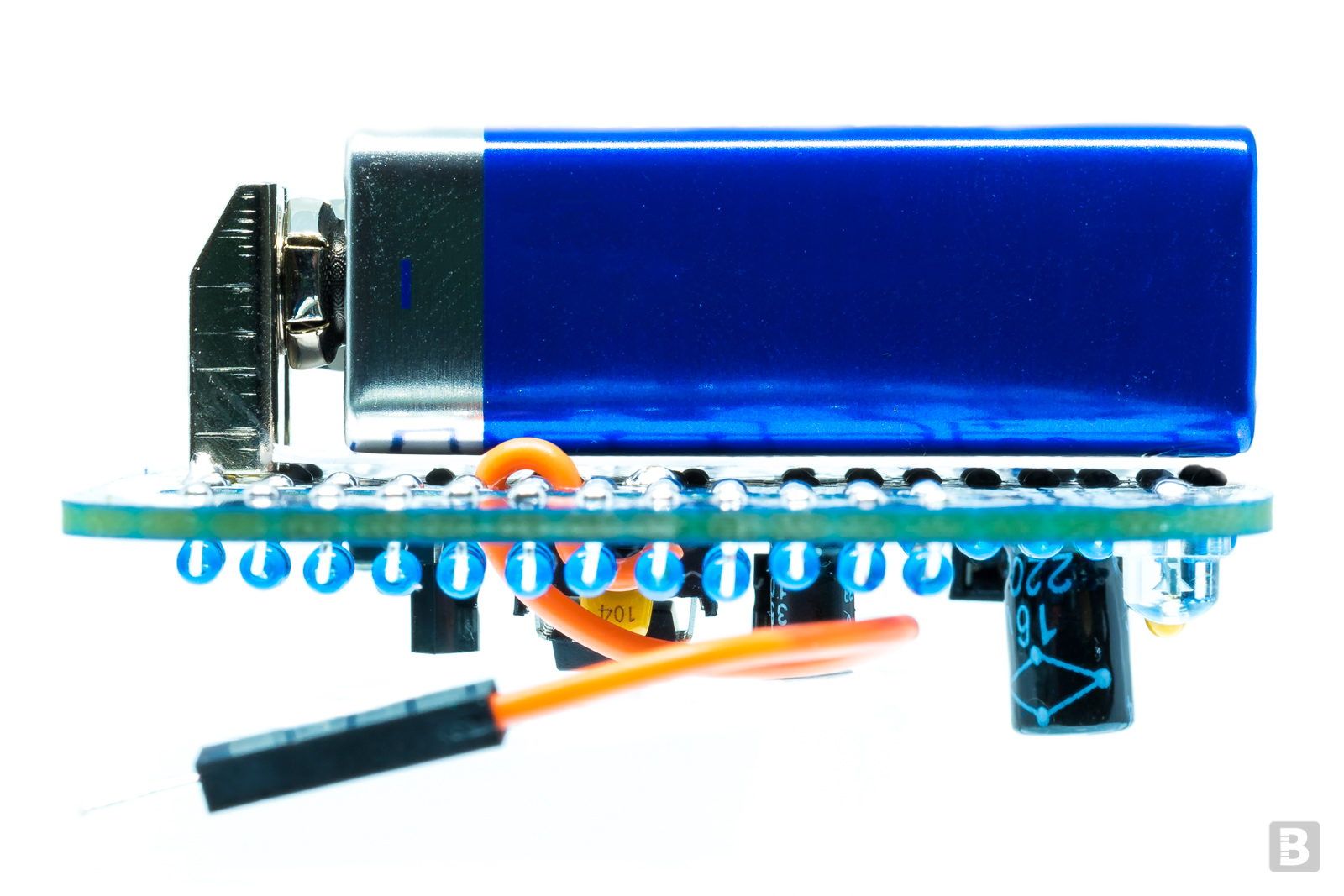
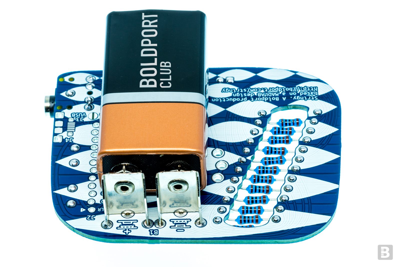
Important: Most 9V batteries have a metal body. Make the contacts as flat as possible. Use the bit of rigid wire supplied to prop the battery up at the bottom so that the metal body doesn't touch the contacts. Shorting contacts will not be good at all! For extra assurance, cut the marked card box and place it under the battery.
IC1 and T1 look identical except for the small writing on the face of the package. Make sure that you solder the correct one into the correct footprint.
The audio jack J1 can be placed on either side of the board.
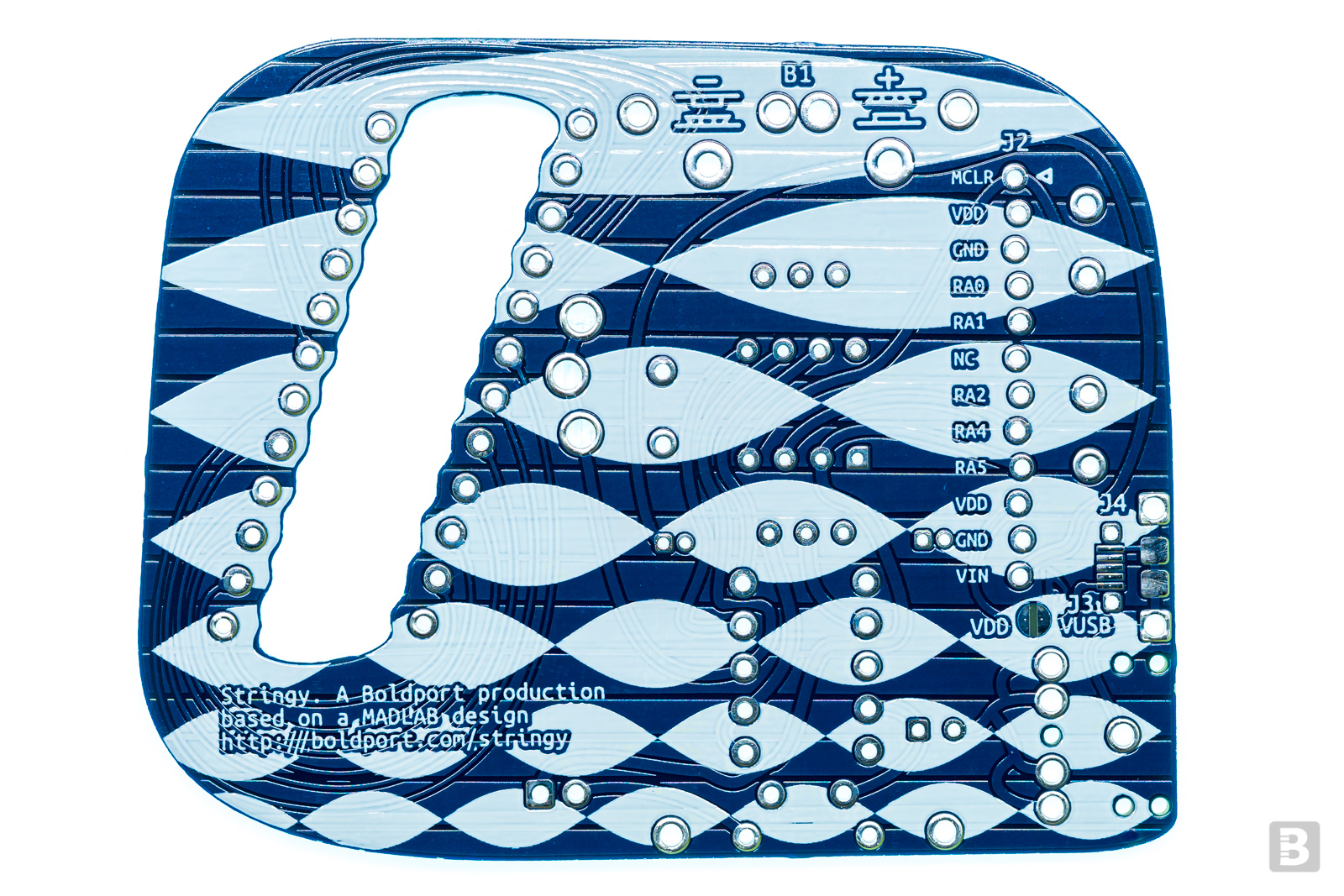
An optional micro USB connector J4 can provide power to the board instead of a battery. You'll need to jump J3 using a solder blob first; this connects the USB power to VDD. Remember to never connect both USB power and the battery.
Interaction
Increase or decrease the octaves using the buttons. Momentarily pressing both buttons simultaneously will switch between acoustic and electric guitar sounding output. When this happens the LED will flash twice.
Pressing both buttons for longer will play a tune; pressing any button will cancel this.
Use the battery as an on/off switch; we recommend that you remove the battery when Stringy isn't used as the circuit draws a small amount of current even when not playing a tune. This will make the battery last longer.
A more detailed description is available here.
Header J2 'breaks out' all the pins of the chip. The top six pins — pin 1 is marked by a triangle — are compatible with Microchip's PICKit programmer. The PIC's pin RA0 is not used in the design and is pulled low. Maybe you could find a good use for it? The code the PIC is programmed with is here ;)
Additional information
We'd like to thank Microchip for providing us with excellent prices for the PICs.
Community site contributions for this project
Open source circuit board design files


