
PissOff


PissOff
Attention ;)
This project is now available at Pimoroni! Click here to go there.
An angry barking blue-in-the-face mad proximity sensor
Once turned on it calibrates to its environment and then detects an object approaching (well, let's face it, a cat, this is about cats). At a certain threshold it starts the mad barking.
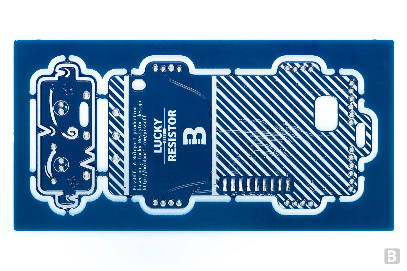
The project is based on original brilliant work by LuckyResistor. We've collaborated to bring this project to Boldport Club members, although the highly optimised MCU code — every bit is sacred, every bit is great — is solely the work of LuckyResistor.
PissOff was project #9 of the Boldport Club.

What’s included?
Here is a list of components that come with the kit
1x Kinetis E series, ARM Cortex-M0+ SOIC20 32 bit MCU, NXP MKE04Z8VWJ4
1x Audio power amplifier SOIC8 IC, TI TPA301DR
1x microSD SMD card socket, MOLEX 1051620101
1x 50KΩ SMD trimmer, Bourns TC33X-2-503E
1x 29mm round speaker, Pro-signal ABS-205-RC
1x 3xAAA battery holder with switch, TruPower SBH431-1AS
1x 3.3V LDO voltage regulator, Diodes AP2210K-3.3TRG1
1x 5mm IR phototransistor (black lens), Multicomp OFT-5301
1x 5mm IR diode (blue lens), Kingbright L-7113F3BT
1x n-channel SOT23 SMD MOSFET transistor, ON Semiconductor 2N7002ET1G
2x 0.1µF 0805 SMD ceramic capacitor, Multicomp MC0805B104K500CT
5x 1µF 0805 SMD ceramic capacitor, Multicomp MC0805F105Z160CT
11x 8.2KΩ 0805 SMD resistor, Multicomp MCWR08X8201FTL
5x 1KΩ 0805 SMD resistor, Multicomp MCWR08X1001FTL
3x 220Ω 0805 SMD resistor, Multicomp MCWR08X2200FTL
7x 47KΩ 0805 SMD resistor, Multicomp MCWR08X4702FTL
1x 33Ω through-hole resistor, Multicomp MF25 33R
1x Yellow 0805 SMD LED, Kingbright KPT-2012YC
14 cm of 20AWG wire, Belden 566-8020
1x Lovely PCB
Batteries are not included.
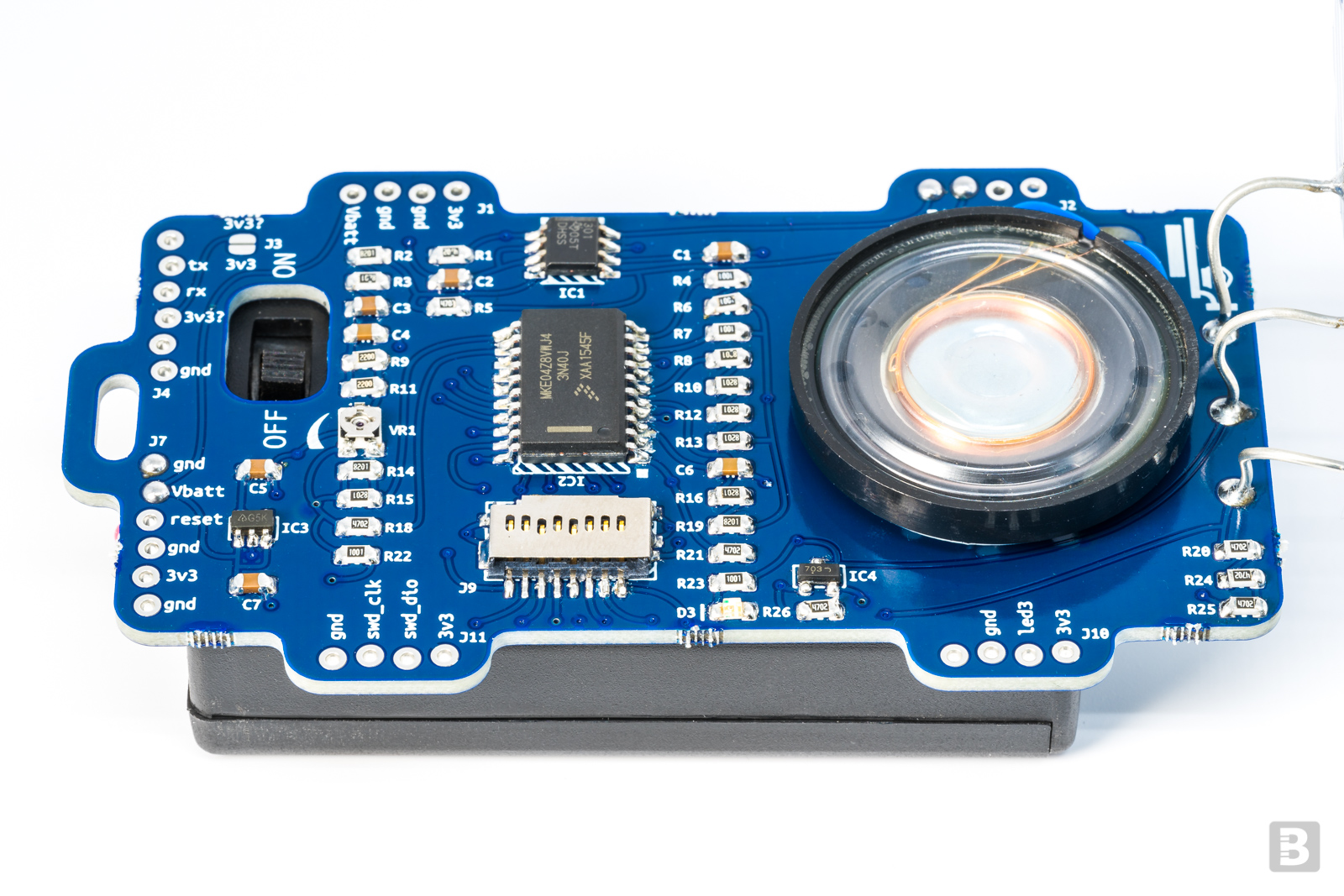
The circuit
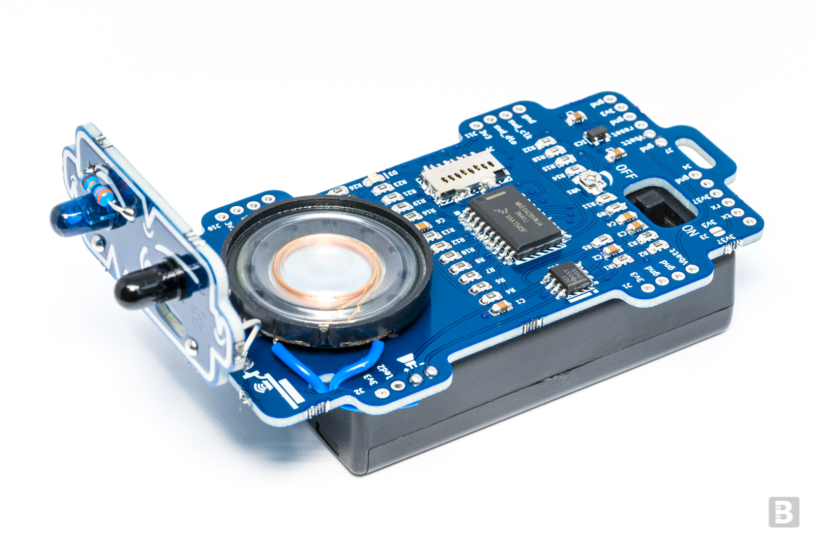
The circuit transmits infrared (IR) signals and then measures the amount of reflected energy. At a certain threshold of reflected energy it reads an audio file from the microSD card and plays it. We recommend barking. (In theory, if you insist, it could also be an enticing call for your cat Jimmy to eat the lovely roast that you just took out of the oven and planned to serve for guests from Argentina... we don't care!).
Schematics 1/2 · PDF
Assembly
COMPONENTS
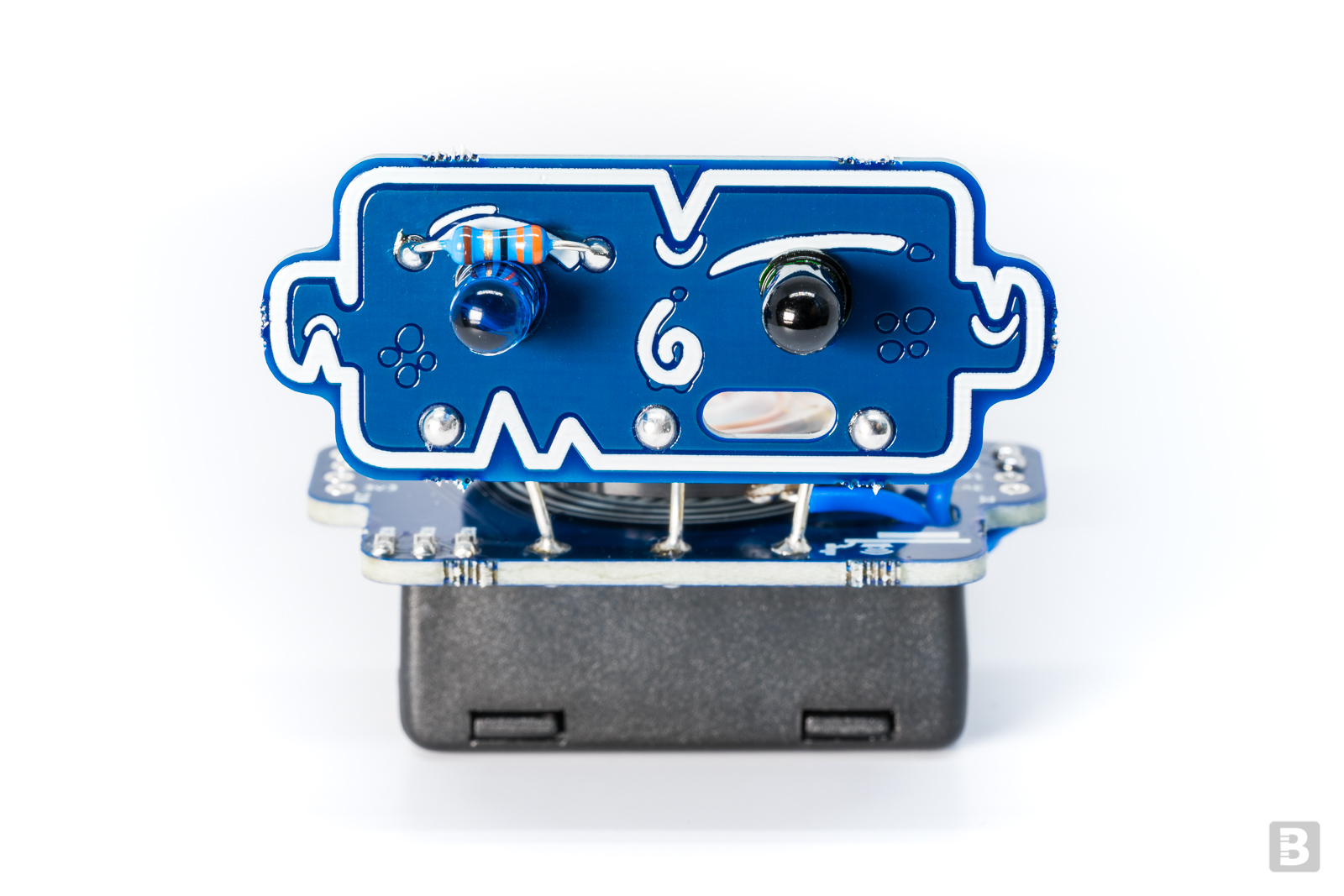
We recommend that you solder the components while the individual boards are still attached to the 'frame'. Pay attention to polarity: a dot or a bar that corresponds to a marking on the board. For LED D3, the arrow points to the cathode, where the bar is. For D1 and D2 make sure that you place the correct components (D1 is black, and D2 is blue) and at the correct polarity, as indicated on the board. (Note that on the printed schematics D2 was erroneously labelled as D5).
If you'd like to use solder-paste, we've arranged for OSH Stencils to sell a stencil for the board at a 15% discount! Just use this link to add the stencil to your order (the discount will already apply).
The resistors have their value printed on them (use this guide to figure out what the codes mean). Capacitors don't have their values printed on them; for this we've marked the 1uF capacitors with a black line across the strip in this kit.
Schematics 2/2 · PDF
FACE, BATTERIES, AND SPEAKER
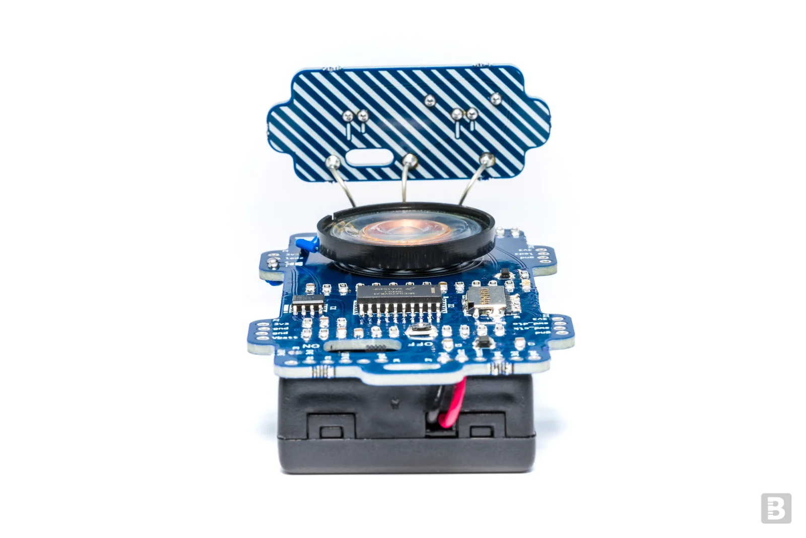
The 'face' is electrically connected to the main board using three rigid wires. Cut the piece of wire in the kit to three equal segments and solder the corresponding holes in the main and face boards. Once that's done you can snap the boards out of the frame. Use a file to remove excess fragments from the break points.
The battery holder takes 3 AAA 1.5V batteries. It has two wires; the red is power (Vbatt) and the black is ground (gnd). Those wires are long so we'll cut them to about half their length and solder them to the speaker. Solder the wires to each of the two most 'external' pads of the speaker. Then solder the other end to the speaker pins on header J2. Even though there is a '+' and '-' on the board the polarity doesn't matter for this speaker.
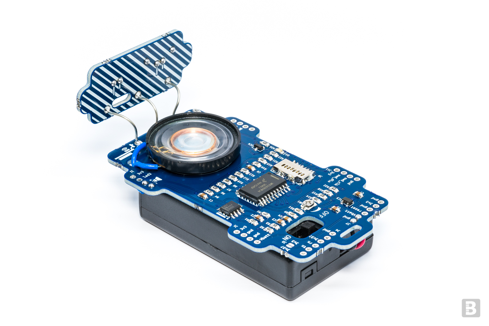
Now solder the red and black wires from the battery pack to Vbatt and gnd, respectively, on header J7. Place the battery pack under the board so that the power switch pokes through the corresponding hole in the PCB. For both the speaker and battery pack use double-sided tape, Blu-Tack, or some other sticky stuff to hold them in place. This isn't mandatory, though.
MICRO-SD CARD SOUND FILE
The audio file is stored on a microSD card. It is loaded onto the card just like you'd load any other image, like those for a Raspberry Pi operating system, for example. Get the sound file and read more information about the process at LuckyResistor's project page.
TURNING IT ON!
When all components are placed and speaker and batteries connected, point the 'face' to a clear area and change the switch to the 'ON' position. Wait a couple of seconds for the MCU to calibrate to its environment and then put your hand in front of the face; you should then hear the barking! Congratulations; you can now protect your food from Jimmy the cat.
If you don't hear barking then try the following:
Turn the potentiometer VR1 all the way counter-clockwise using a screwdriver. This sets the volume to maximum.
Check that the switch is indeed at 'ON' and that there is power coming through to the board (about 4.5V)
EXTRAS: SERIAL INTERFACE AND PROGRAMMING
The software for the MCU has been authored by LuckyResistor with a comprehensive guide here.
As a summary, one can connect the board to a serial port useful debug information — simply connect at 112500 baud through header J4 — and type 'main' after connection and then 'help' to see options. The MCU comes programmed so it should 'just work' without programming. If you wish to re-program the MCU, you'll need an SWD programmer to connect to J11.
Further information
Community site contributions for this project
Open source circuit board design files
