
Cordwood Puzzle Three


Cordwood Puzzle Three
Attention ;)
This project is now available at Pimoroni! Click here to go there.
A Third in a series of cordwood puzzles
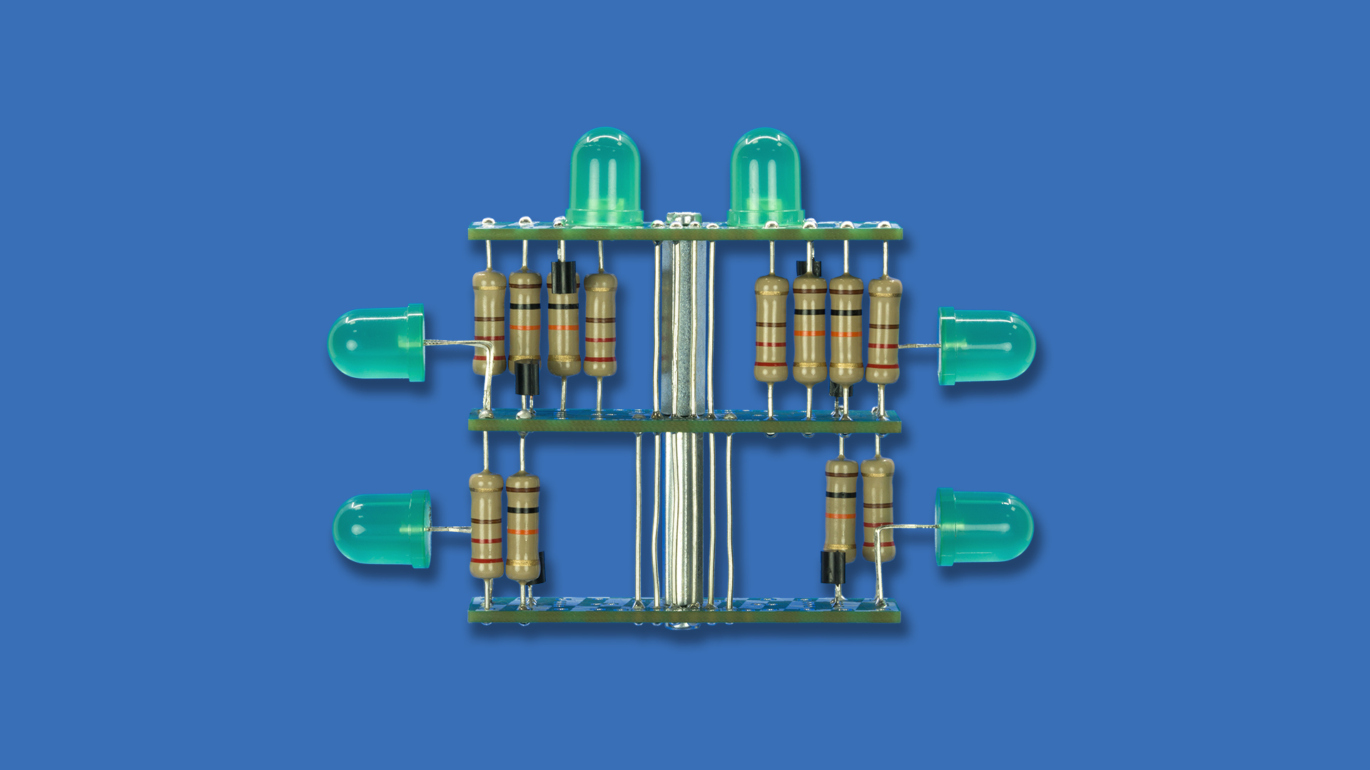
This is our third Cordwood Puzzle, appropriately having three levels! (Here are the first and second puzzles.)
In the 1950s and 1960s inventive engineers saved space by using the 'cordwood' assembly, where components were sandwiched in between two circuits boards. This construction became less useful with reduced component sizes, PCB manufacturing advances, more compact integration, and surface mount technology, but is still a lovely piece of history. Combining both old and new, the Cordwood Puzzle series of projects are a tribute to this construction and to the engineers who came up with it.
The puzzle is to correctly assemble the circuit with the components at hand. Once completed, all LEDs light up when power is applied. When connected to a controller board each LED can be individually controlled.
Unfortunately(!), all the comprehensive assembly guides were mysteriously missing from the kits.
Cordwood Puzzle Three was project #25 of the Boldport Club.

What’s included
Saving space back in the day. Source
6x 220Ω 2W resistor, Multicomp MCF 2W 220R
6x 10KΩ 2W resistor, Multicomp MCF 2W 10K
6x MOSFET n-channel transistor, Fairchild 2N7000_D26Z
1x 1µF ceramic capacitor, AVX SA305E105MARC
6x 10mm green LEDs, Kingbright L-813GD
1x 25mm M3 female-female standoff, ETTINGER 05.03.251
1x 25mm M3 female-male standoff, ETTINGER 05.13.251
2x M3 screws, DURATOOL M38 CSSTMCZ100-
1x 10-pin 2.54mm header, Multicomp MC34739
5x 6cm of 20AWG wire
3x Lovely PCBs
Assembly inforgraphic | PDF
Assembly
Assembly inforgraphic | PDF
Challenge yourself by assembling the kit without further instruction. Before you do that, however, note the following:
when connecting to a board, make sure that the I/Os can tolerate the voltage levels that are applied to the Cordwood;
make sure that you do not short power and ground; and
don't exceed 20mA per LED.
Even though the original comprehensive are forever lost, we've created an alternative guide of varying difficulty levels. Use any information from the infographic, or don't. Up to you! Finally, the assembly instructions for the first Cordwood Puzzle could be helpful ;)
Or, you could follow Saar building it on camera!
Additional information
Community contributions for this project
Open source circuit board design files
