
shimmy's back!
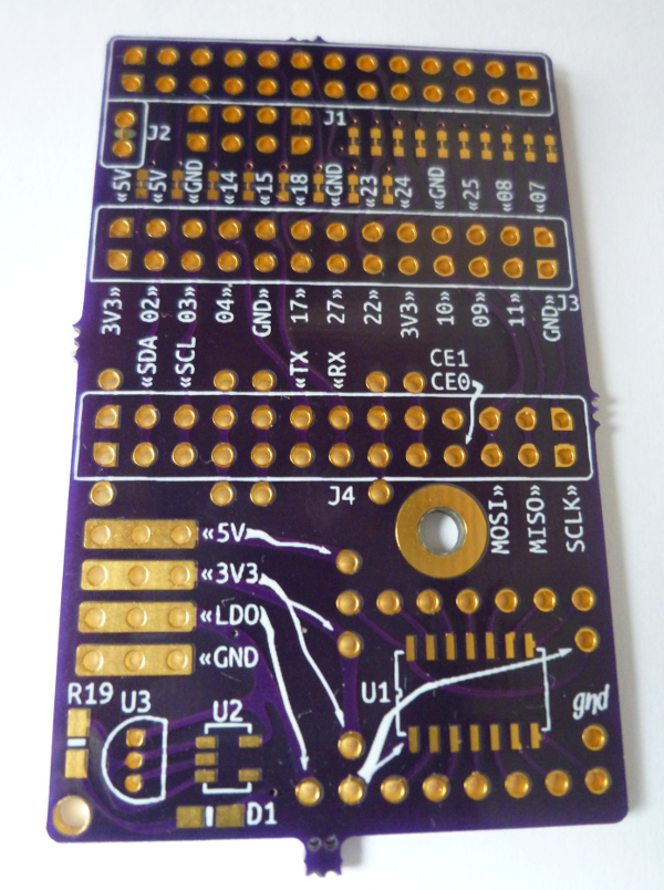
'shimmy' is a Raspberry Pi "hackable" daughter card and is the second board manufactured with PCBmodE. The primary purpose for 'shimmy' was to test dual-sided boards, and the generated Excellon drill
file. Six shimmys are now back from OSH Park; below is the analysis.
Drills:
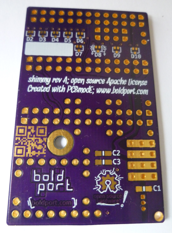
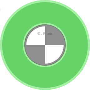
The 155 drills are all aligned, so I'm confident that the Excellon data is correct. I should have made the copper rings around the pads a bit larger, particularly for U3, though. The large mounting hole (shown on the left) was meant to be non-plated with a ring around it, and that came out as it should have. The smaller hole (shown to the right) in the left corner of the board was meant to come out non-plated as well, but came out plated. (In the figures the light green is lack of soldermask, and dark green is copper.) I assumed -- wrongly -- that since there was no copper surrounding the small hole, it wouldn't be plated, and the small bit of copper within the drill diameter would be drilled out. In the future, I'll have to either draw a ring as with the mounting hole, or be more explicit about non-plated holes (there was a single drill file, so I wasn't as explicit as some manufactures require, btw).
QR code:
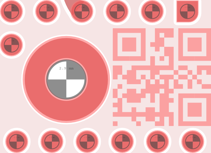
The QR code is made of an exposed (that is, lack of soldermask) copper plane on the bottom layer.
When I printed the QR code with 1:1 scale it worked without a problem, though when I got the board, the Android app on my phone wouldn't read it no matter what I tried. Over breakfast I happened to see another QR code on a piece of paper and realised the problem -- the QR code on 'shimmy' is colour inverted! <facepalm>. The bits that appeared dark on paper, appear light (silver/gold) on the board over the dark (purple) soldermask.
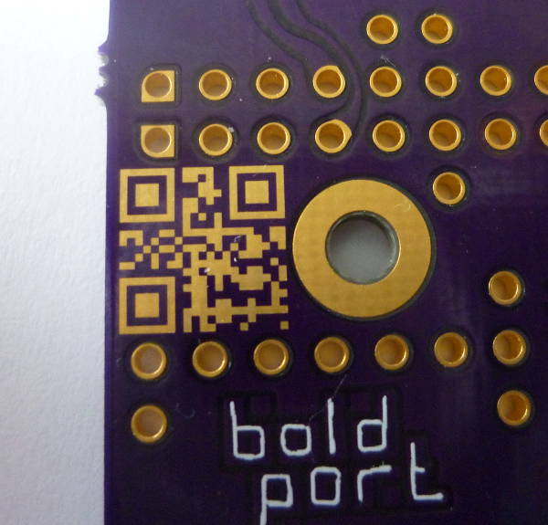
It turns out that most QR code apps do not support inverted codes, though I found an app -- NeoReader -- that does, and it reads the code without a problem. Next time I should take this inversion into account and simply invert the code and perhaps add a border around it.
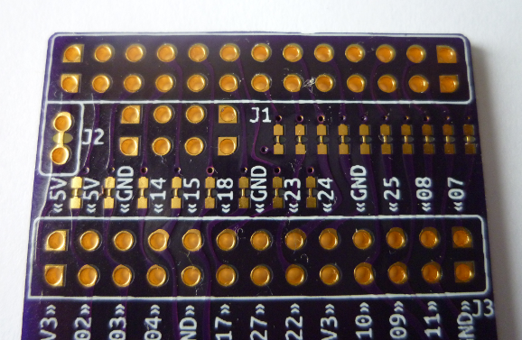
Silkscreen:
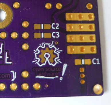
The silkscreen did not come out as nicely as with 'pieceof', which was manufactured with (the more expensive) Eurocircuits. That said, everything is legible so that's not a problem. (Next time I'd make the drawing near D8 a bit larger, though).
Unfortunately, four of the six boards have misaligned silkscreen on the bottom side. Since this misalignment appears only on a subset of the boards, I suspect that it was caused by a manufacturing problem, and not due to PCBmodE's Gerbers -- I'll need to confirm this with OSH Park, and make sure that nothing was missing from the Gerbers / design that could have helped prevent this.
Soldermask:
'shimmy' is meant to be 'hackable', by which I mean that cutting and patching traces is expected. For this, I exposed some of the traces so that they could be easily cut or scraped off. For example, all the resistors in series with the I/Os are shorted so that the board works without needing to solder anything on the pads (like a 0 Ohm resistor). Another example is J2, which carries the 3.3 V rail from the RPi through the GPIO header to the rest of the card. The idea is that if one decides to use the optional LDO on 'shimmy', the short can be cut, and a patch from the LDO header can be connected to the bottom pin of J2 to supply the card with that rail instead. (The amount of current that can be sourced from the RPi's 3.3 V rail is very limited, so the additional LDO could come in handy.)
Overall, a good run. I promised four people over on Twitter a free 'shimmy' and I hope they'll make good use of it -- I plan to dispatch them later on this week. I'd like to create more of this card with some modifications, so if you're interested in buying one please let me know.
 |
| 'shimmy' top |
 |
| 'shimmy' bottom |
Drills:
 |
| Small hole |
 |
| Large mounting hole |
QR code:
The QR code is made of an exposed (that is, lack of soldermask) copper plane on the bottom layer.
 |
| QR code |
When I printed the QR code with 1:1 scale it worked without a problem, though when I got the board, the Android app on my phone wouldn't read it no matter what I tried. Over breakfast I happened to see another QR code on a piece of paper and realised the problem -- the QR code on 'shimmy' is colour inverted! <facepalm>. The bits that appeared dark on paper, appear light (silver/gold) on the board over the dark (purple) soldermask.
It turns out that most QR code apps do not support inverted codes, though I found an app -- NeoReader -- that does, and it reads the code without a problem. Next time I should take this inversion into account and simply invert the code and perhaps add a border around it.
Silkscreen:
The silkscreen did not come out as nicely as with 'pieceof', which was manufactured with (the more expensive) Eurocircuits. That said, everything is legible so that's not a problem. (Next time I'd make the drawing near D8 a bit larger, though).
Unfortunately, four of the six boards have misaligned silkscreen on the bottom side. Since this misalignment appears only on a subset of the boards, I suspect that it was caused by a manufacturing problem, and not due to PCBmodE's Gerbers -- I'll need to confirm this with OSH Park, and make sure that nothing was missing from the Gerbers / design that could have helped prevent this.
 |
| Silkscreen is a bit off |
 |
| What the silkscreen should have looked like |
Soldermask:
'shimmy' is meant to be 'hackable', by which I mean that cutting and patching traces is expected. For this, I exposed some of the traces so that they could be easily cut or scraped off. For example, all the resistors in series with the I/Os are shorted so that the board works without needing to solder anything on the pads (like a 0 Ohm resistor). Another example is J2, which carries the 3.3 V rail from the RPi through the GPIO header to the rest of the card. The idea is that if one decides to use the optional LDO on 'shimmy', the short can be cut, and a patch from the LDO header can be connected to the bottom pin of J2 to supply the card with that rail instead. (The amount of current that can be sourced from the RPi's 3.3 V rail is very limited, so the additional LDO could come in handy.)
Overall, a good run. I promised four people over on Twitter a free 'shimmy' and I hope they'll make good use of it -- I plan to dispatch them later on this week. I'd like to create more of this card with some modifications, so if you're interested in buying one please let me know.