
MOSTAP


MOSTAP
Attention ;)
This project is now available at Pimoroni! Click here to go there.
A touch sensitiveblast from the past
At a time when powerful processors are so cheap and much of their functionality left unused in a typical application, it’s delightful to look back to hobbyist electronics projects from forty years ago, and admire the optimised design and the skill of those who created them. MOSTAP is a digital version follow-up to Boldport Club's Project #5, The TAP.
In the second issue of Elektor magazine in English, February 1975, MOSTAP appeared as an improved — digital vs analogue — version of The TAP. We've re-created it for the enjoyment of those who may appreciate the elegance of the design today. The original article describing the functionality of the circuit is here.
MOSTAP was project #17 of the Boldport Club.

What’s included
6x 10MΩ resistor Multicomp MCF 0.25W 10M
6x1MΩ resistor Multicomp MCF 0.25W 1M
1x 2.7MΩ resistor Multicomp MCF 0.25W 2M7
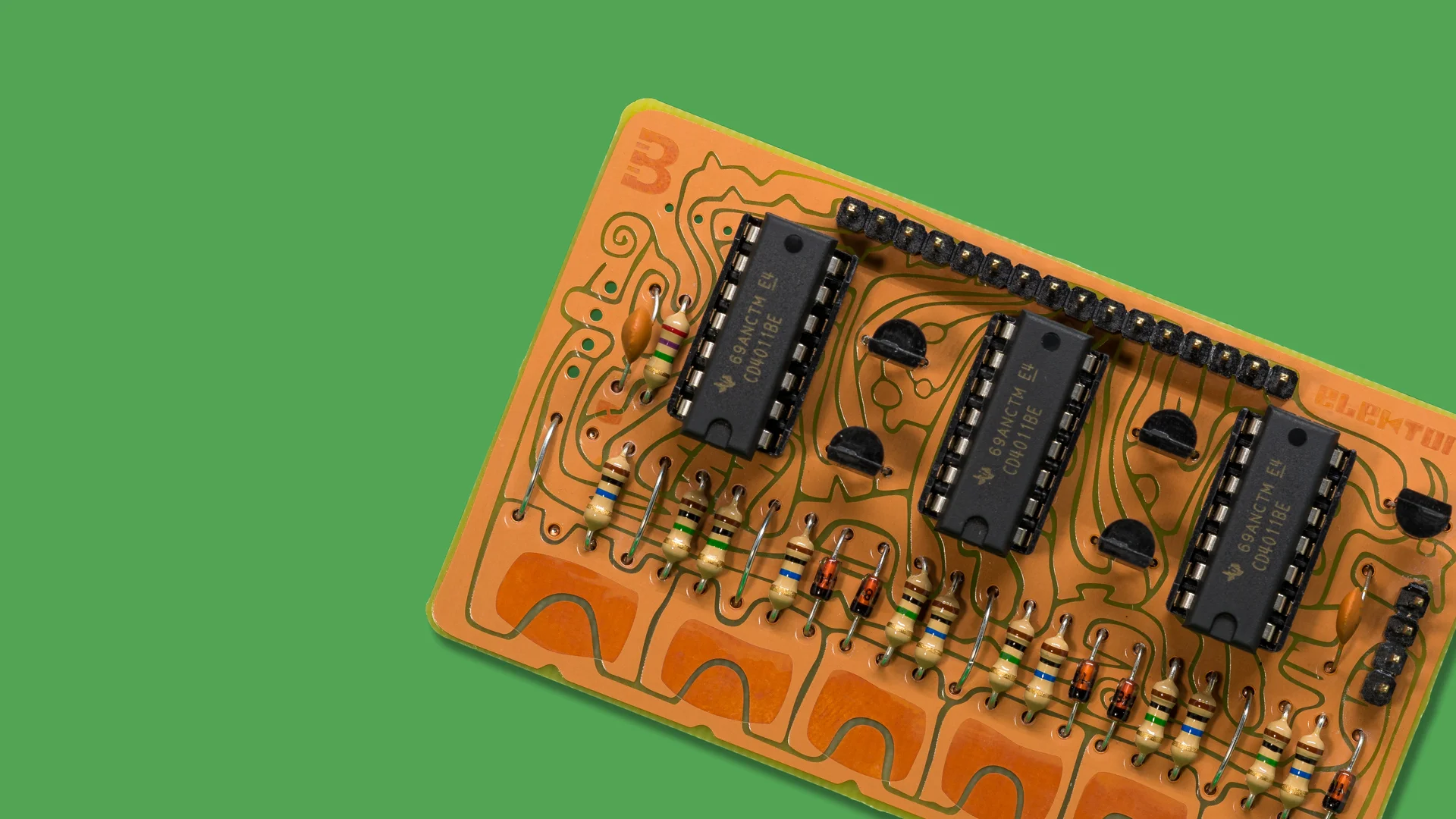
3x Quad 2-input NAND gate TI CD4011BE
3x IC DIP 14 contact socket TruConnect DS1009-14
1x 20-pin 2.54mm header Multicomp MC34739
5x MOSFET n-channel transistor Fairchild 2N7000_D26Z
1x 47nF capacitor Suntan TS15001H473MSBUB0R
1x 470pF capacitor Suntan TS15001H471KSBPA0R
5x Small signal diode Diotec 1N4148
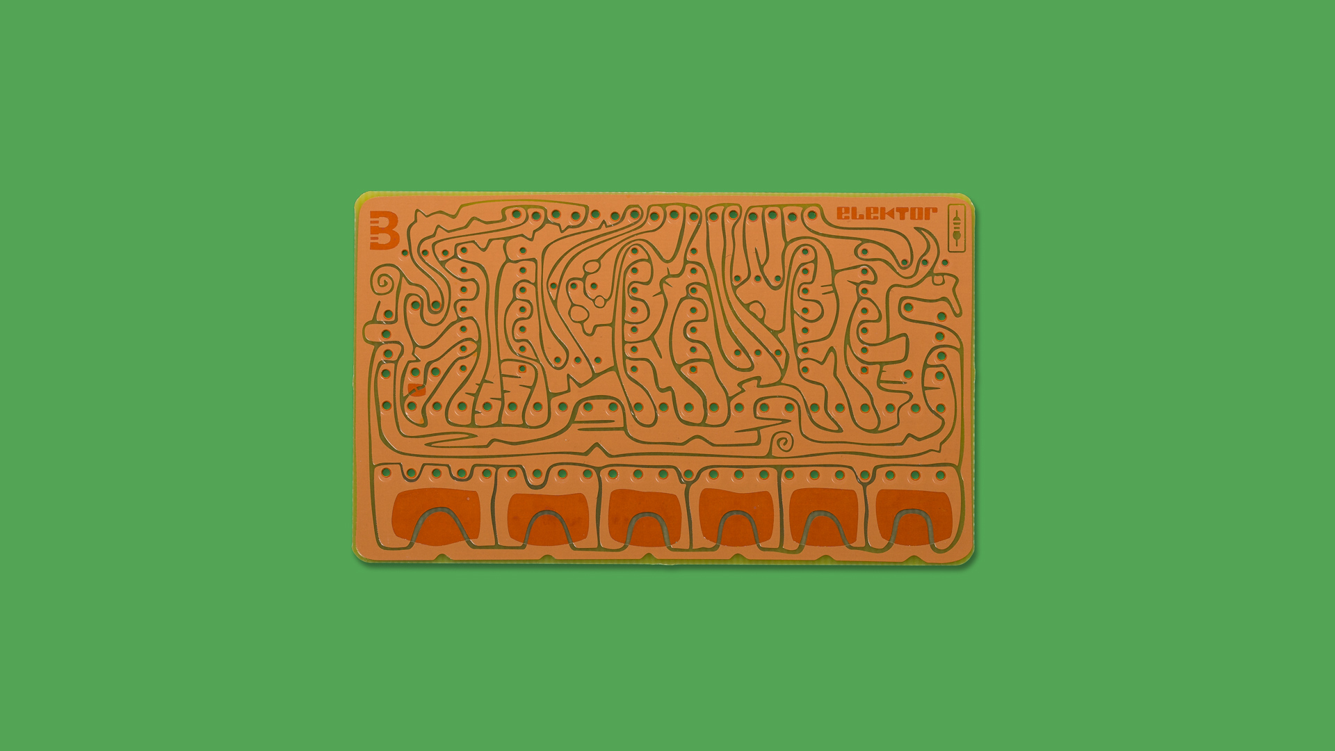
1x Lovely lovely copper PCB
Assembly and usage
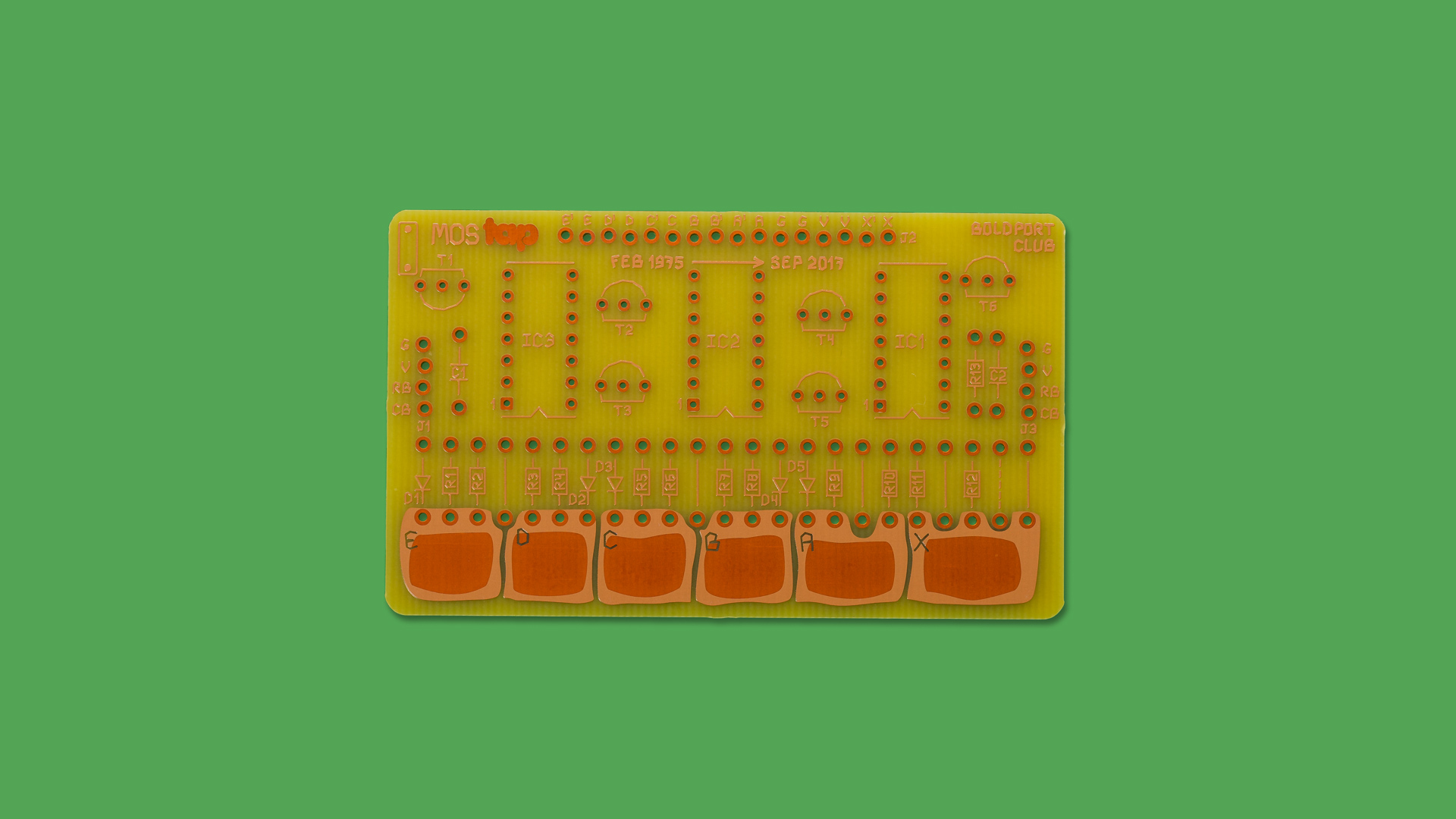
The MOSTAP has five 'touch' buttons A through E — they work by either shorting the button with ground through skin conductivity, or through 'detecting' the mains hum through our body — only one active at any one time. A reset (X) button turns off the active button.
The project includes the following components
To keep with the authentic feel of the original boards, the PCB comes without a 'finish' that is normally applied to PCBs during manufacturing to help with solderability, and prevent the oxidation of the copper. Therefore, soldering onto exposed copper is harder than usual. To help with this please
1. Clean the entire board using alcohol to remove any coating, oils, dirt, and existing oxidation.
2. When soldering, pay attention that that the solder flows into the hole to make a good contact. This may require leaving the iron for longer on the pad. A good way to verify this is to look on the other side of the hole and see that a bit of soldered flowed through.
Make sure to place components on the right side as indicated by the pictures on this page and the component polarity symbol on the PCB.
Schematic | PDF
Follow the schematic to assemble the project. The solid lines across pads indicate a wire jumper — use clippings of resistor legs for those. In the schematic the shaded Cx and Ca-Ce can optionally be added to improve noise immunity. Other shaded components and dashed lines do not need to be populated unless you intend on chaining multiple MOSTAPs, as described in the original Elektor article.
Each 'button' has two outputs, indicated as N or N' (A, A', B, B', etc.) The N output comes directly from the NAND-gate IC and can only drive less than 1mA of current per pin. This is normally not enough for driving a load like an LED, and drawing excessive amount of current from the pin can damage the device. For driving loads like LEDs, use N', which is a MOSFET controlled by the N output.
Additional information
Community contributions for this project
Open source circuit board design files
