IxpandO


IxpandO
Attention ;)
This project is now available at Pimoroni! Click here to go there.
A 16 bit I²C IO expander
IxpandO is an input/output expansion board based on Microchip's MCP23017. When you run out of inputs or outputs for your project, use this project to connect up to 16 of them through an I²C interface.
IxpandO was project #17 of the Boldport Club.
What’s included
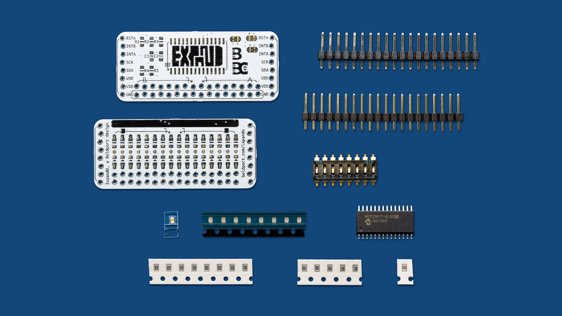
1x 16bit I2C IO expansion IC, Microchip MCP23017T-E/SO
1x 10µF 0805 SMD ceramic capacitor, Multicomp MC0805X106K160CT
1x 1µF 0805 SMD ceramic capacitor, Multicomp MC0805F105Z160CT
5x 4.7KΩ 0805 SMD resistor, Multicomp MCWR08X4701FTL
8x red 0805 LEDs, Kingbright KPT-2012EC
8x 1KΩ 0805 SMD resistor, Multicomp MCWR08X1001FTL
1x 8-wide DIP/SIP switch, Multicomp MCEMR-08-T
2x 20-pin through-hole header, Multicomp MC34739
2x PCBs
Infographic | PDF
Assembly and usage
Use the infographic for correctly place the components. Two identical PCBs are provided with the project. You're able to use a single board by populating both sides, or stack two boards to create a 3D construction.
The header pins are staggered so there is no need to necessarily solder them in place.
Several boards can be changed using the side headers. To do this, you'll need to set each board to a different I²C address from the default 0x20 one. This is done by cutting the track on the solder blob jumper and then soldering a blob to VCC or GND.
Any I²C driver will work with this chip; an Arduino driver is available from Adafruit. We've chosen a 4.7KΩ pull-ups on SDA/SCL for versatility (this should work with 100kbit/s to 400kbit/s standard rates under most conditions). The chip, however, can go up to 1.7Mbit/s although the pull-ups values may need to be changed depending on rate and other conditions, such as the properties of the driver, cable lengths, etc.
According the datasheet, each I/O can sink or source 25mA, although there is a total limit of 125mA, so be aware not to exceed that limitation.
Further information
Community contributions for this project
Open source circuit board design files


