Pease-out


Pease-out
Attention ;)
This project is now available at Pimoroni! Click here to go there.
Another tribute to Bob Pease
Bob Pease was an expert analogue designer who developed seminal circuits that are still with us today. Our first tribute to Pease was our first ever Boldport Club project, and this current one is the last ‘monthly’ project.
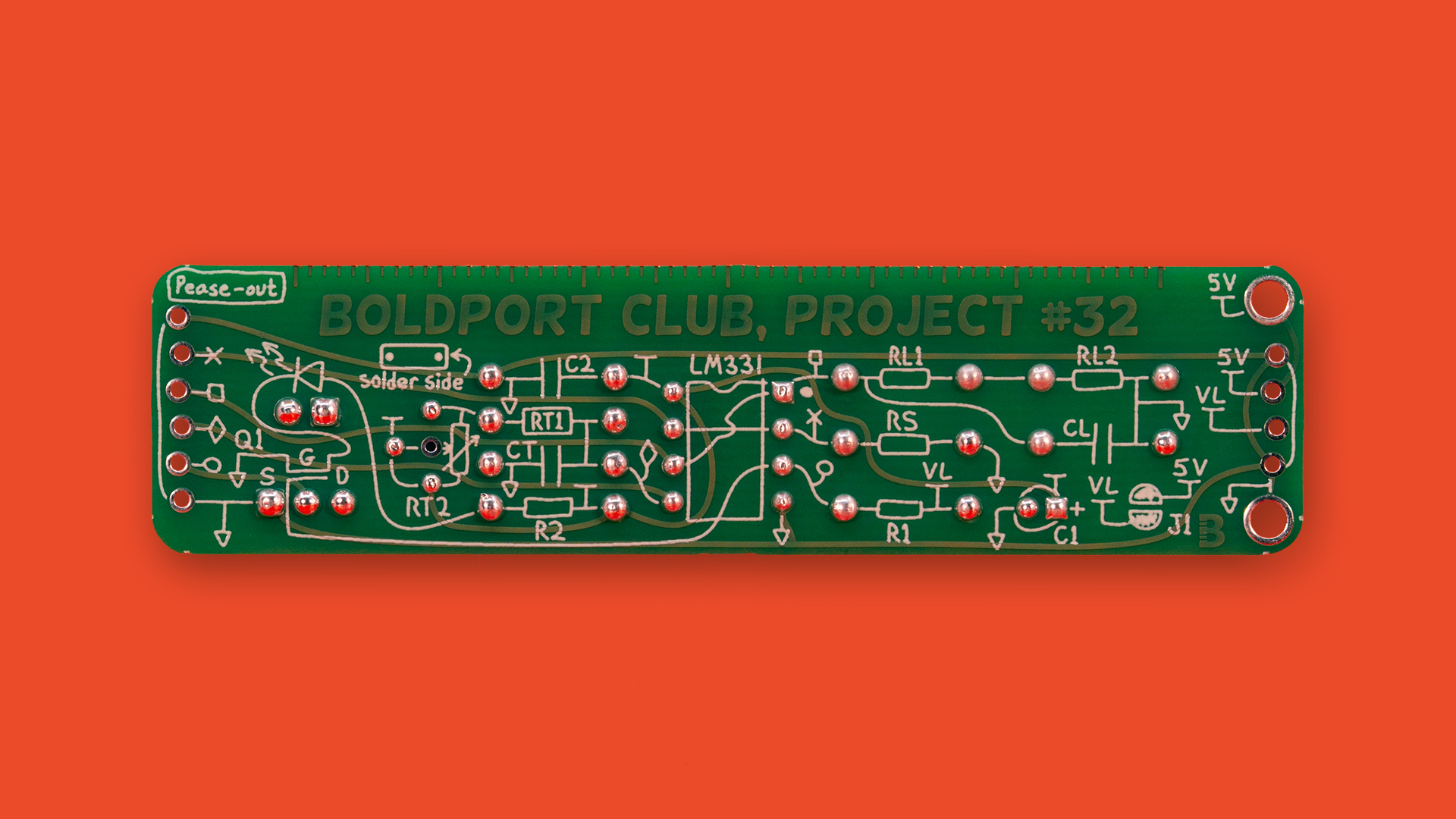
This version uses a circuit around the LM331, also designed by Pease. It is a sinle voltage to frequency converter where the setting of the trimmer sets the output frequency that can be observed by the flashing LED. The frequency range using the multi-turn 2MΩ trimmer is about 3Hz to 300Hz.
The circuit itself appears in Application Report SNOA735B, Figure 2. One of the primary advantages of this arrangement is that the output isn’t affected (much) with the supply voltage. The Application Report details other advantages.
Pease-out was Project #32 of the Boldport Club.
What’s included
1x LM331 IC, TI LM331N/NOPB
x1 N-channel MOSFET transistor, Fairchild 2N7000_D26Z
1x 5mm red LED, CREE C503B-RBS-CW0Z0AA1
1x 2MΩ trimmer, Suntan TSR-3296Y-205R
6x 15KΩ resistor, Multicomp MF25 15K
2x 16-pin IC socket, TruConnect 22-0107
1x 10µF electrolytic capacitor, Multicomp MCUMR16V106M4X5
1x 0.1uF, Suntan TS170R2A104KSBBA0R
2x 1uF, Suntan TS170R1H105MSBFA0R
1x 10-pin header, Multicomp MC34739
1x Lovely PCB
Infographic | PDF
Assembly
Conveniently, the schematic is on the board itself! Follow this infographic for help. Two things to pay attention to in particular:
Place components on the right side! See the symbols on the PCB.
There’s an extra hole that we added to allow people to use other potentiometers. Unfortunately we wired it wrongly (it’s connected to ground). If you’re going to use the components we provided, then everything’s fine. If not, pay attention not to use this hole and potentially creating a power short.
Additional information
Community site contributions for this project
Open source circuit board design files


