Krell
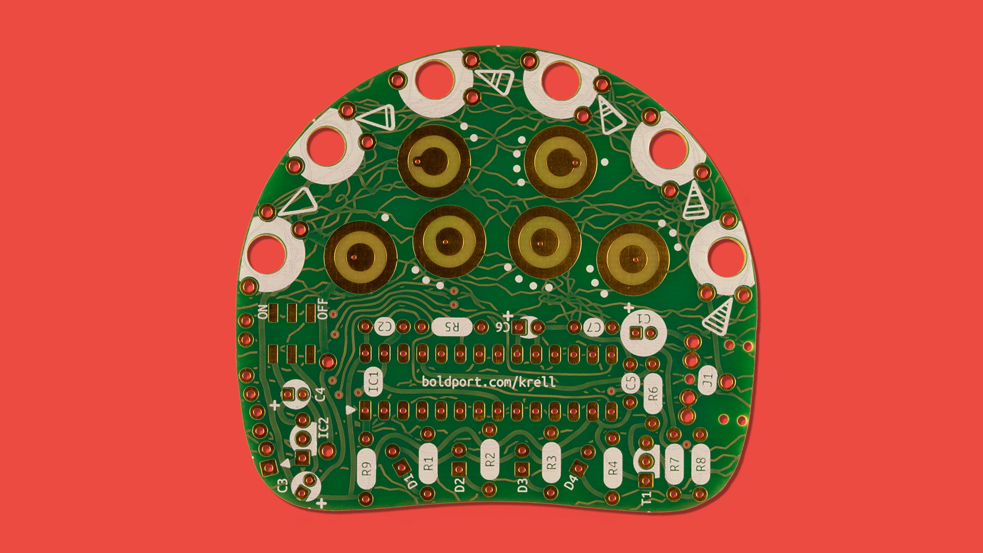
Krell
Handheld electronic tonalities generator
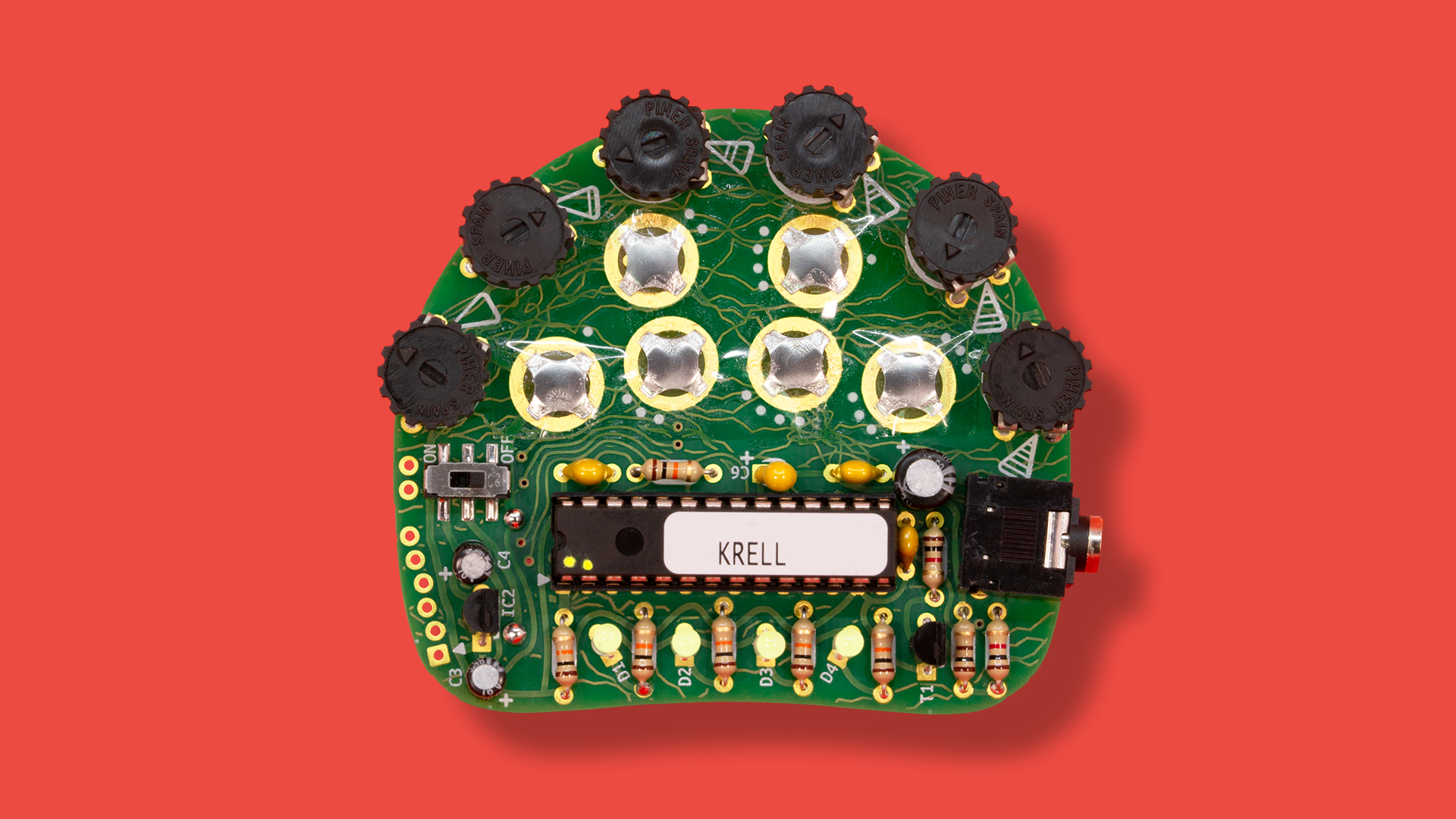
Krell is a small DSP synthesiser that fits into the palm of your hand. Using the buttons and potentiometers you can dial up a range of interesting sci-fi sounds reminiscent of those in the film Forbidden Planet.
The name of the project is derived from the Krell, an absent alien species in the film Forbidden Planet. The film is famous for having the first entirely electronic soundtrack, which was produced by Bebe and Louis Barron. They’ve used simple oscillators, ring modulators, and reverb to produce an eerie alien soundtrack. The Barron’s story of pioneering electronic music, and the trouble they had being credited at the time, is well worth reading.
This project produces very similar sounds by changing the oscillators up and down in frequency and using the modulation and reverb effects.
Krell is our remix of a soldering project by James Hutchby of MadLab. The project was also supported by the kind donation of metal domes from Snaptron.
Krell was project #29 of the Boldport Club.
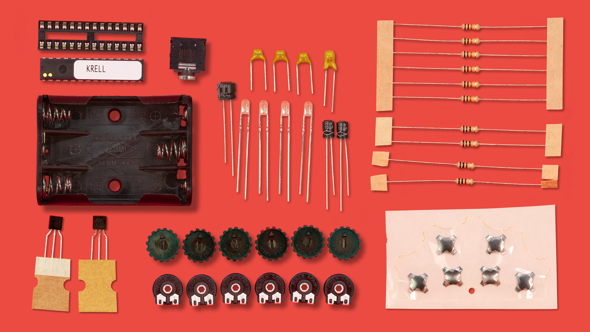
What’s included
1x dsPIC microntroller, Microchip dsPIC33EP128MC202-I/SP
1x 3.3V Regulator, TI LP2950-33LPRE3
1x NPN bipolar transistor, ON BC547CTFR
1x 220μF electrolytic capacitor, Multicomp MCUMR6V3227M6.3X5
2x 10μF electrolytic capacitor, Multicomp MCUMR16V106M4X5
1x 10μF tantalum capacitor, Suntan TS19001C100MSB0A0R
3x 100nF capacitor, Suntan TS170R1H104MSBFB0R
6x 47KΩ trimmer, Piher PT10MV10473A2020-I-PM-S
6x Black thumbwheel, Piher 5034
4x White LED, Valcon VDIFFLED-3mm-W
2x 100Ω resistor, Multicomp MCF 0.25W 100R
1x 1KΩ resistor, Multicomp MCF 0.25W 1K
6x 10KΩ resistor, Multicomp MCF 0.25W 10K
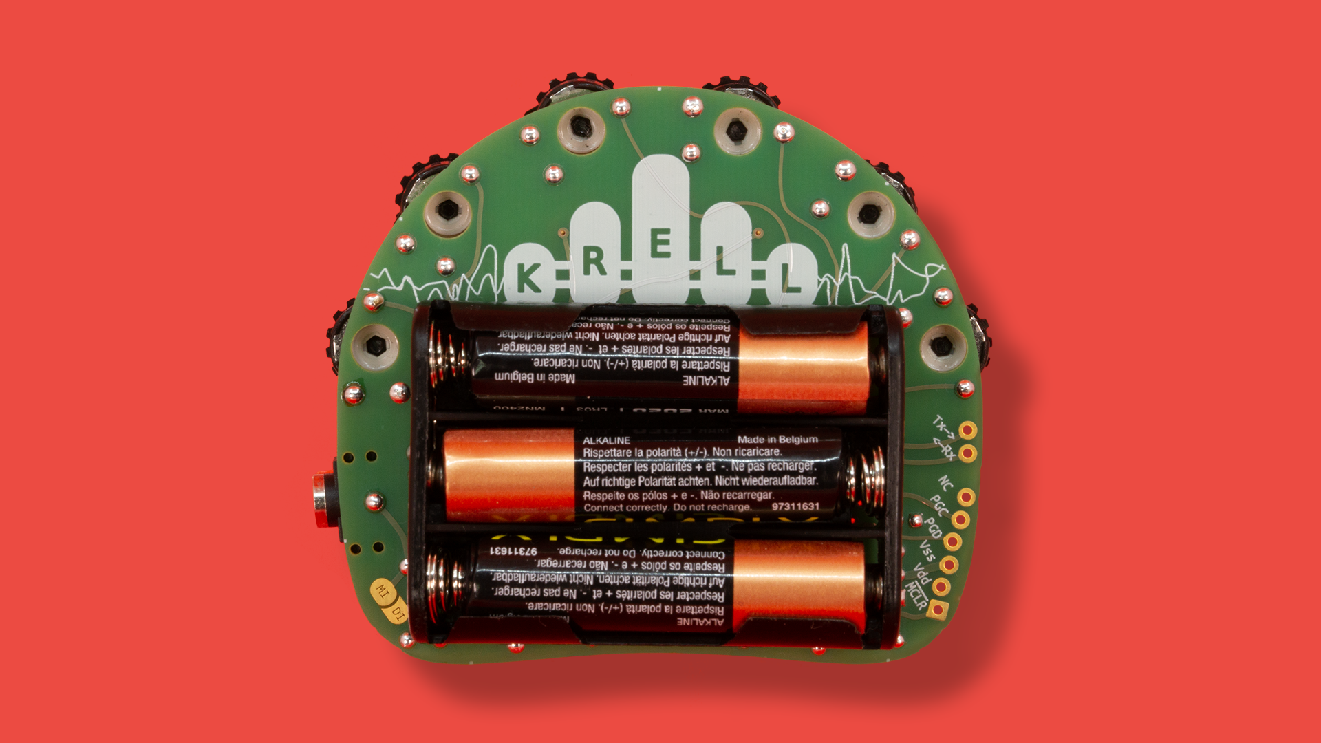
1x Battery holder, TruPower BH 431-1P
1x 3.5mm stereo jack socket, TruConnect 20-0137
1x 28-pin DIP socket, TruConnect 22-0114
1x DPDT slide switch, C&K JS202011SCQN
1x Button sheet, Snaptron Peel-N-Place™
1x Lovely PCB
Krell Schematic | PDF
Assembly and usage
There is a preferred order of assembly that will help since the placement of some components may make others harder to solder. See the assembly infographic for details.
CONTROL
You've built it. Congratulations! But how does it work? For testing that it is indeed working, there are a number of "demo modes". Plug in your headphones or speakers and try pressing button one and three together; this should play a demo sound.
There are many adjustable parameters in the synthesizer; too many to fit on one PCB! To make it possible to change a large number of parameters the controls are accessible in a menu type system. Changing a value is achieved by using the buttons to select the desired control and then changing it with the appropriate trimmer.
Provided with the kit is a card with a table of all the properties that you can change. The top row are the buttons and the left column are the trimmers. Pressing a button and releasing it puts the trimmers in the corresponding column in the "Button released" table. Pressing down the button and keeping it held will put the corresponding column in the "Button held" table. For example, if you wanted to change the pitch of DCO 0, you’d press button 1 once and let go, then adjust the 5th trimmer.
The synthesis engine has four digital controlled oscillators (DCOs) that are mixed together so you hear them all at once. These are DCO 0, DCO 1, DCO 2, DCO 3. Each oscillator has a number of low frequency oscillators (LFOs) that modulates its corresponding oscillators pitch, amplitude and pulse width. Then there are a few effects that can be added to them: ring and frequency modulation, reverb, flanger and fuzz.
More detailed information by MadLab can be found in this PDF document.
TAKING IT FURTHER
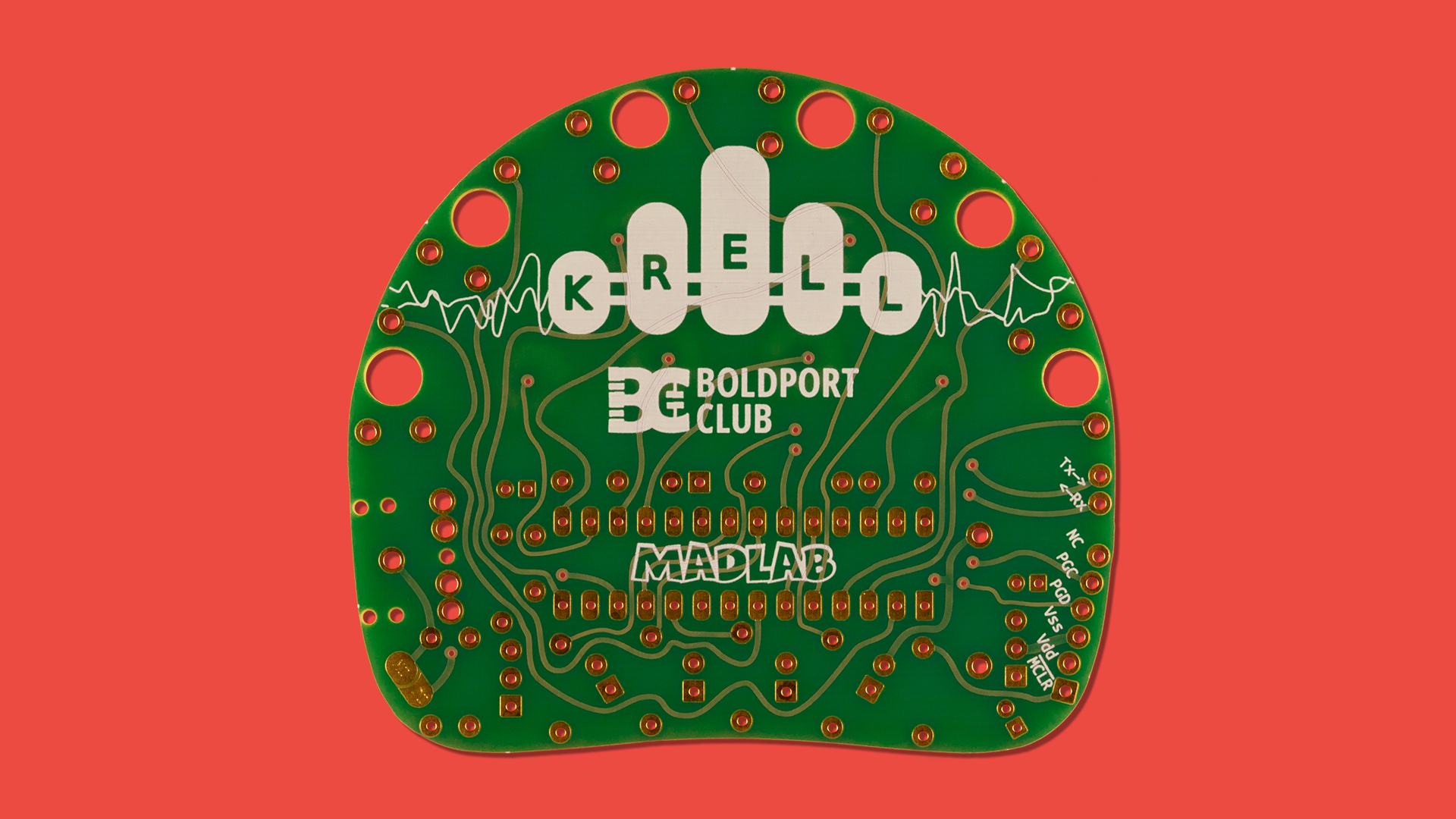
Krell can be re-programmed; there is a header that’s compatible with the PICkit 3 and other PIC programmers. The source code is available in the Zip file here github.com/clubmadlab/Krell
There is also a serial port available, TX and RX are marked. This can be communicated with at 9600 baud. The code that comes programmed on the PIC has a serial control terminal. Try it ;)
The Piher potentiometers used in the project have removable knobs. There are actually a number of different types available from the manufacturer. This is why we left a hole underneath the potentiometer as it allows for back mounting a longer shaft if you wanted to customise the board.
Finally, we’ve added an experimental feature that we haven’t fully tested (so you’ll need to know what you’re doing): a possibility to add MIDI. There’s a jumper labelled MIDI on the jumper’s copper pad. If you join the two pads together the device will try and communicate in the MIDI protocol at 31,250 baud. This should be compatible with most MIDI devices. To interface properly, you should follow the specification of the MIDI standard.
Additional information
Community contributions for this project
Open source circuit board design files


